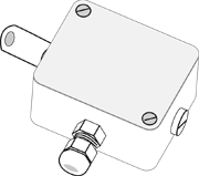
TERMINAL
CONNECTIONS
|
|
HX21
 HX21
Terminal Block
 Remove
Cover Screws for Access
|
Figure
4-1. HX11, HX12, HX13 and HX21 Transmitters
TERMINAL
CONNECTIONS AND WIRE COLORS Table 4-1
|
|
HX11C
|
HX12C
|
HX13C
|
HX21C
|
|
RH
Positive
|
RED
|
A
|
RED
|
A
|
|
RH
Negative
|
BLACK
|
B
|
BLACK
|
B
|
|
Temp.
Positive
|
WHITE
|
C
|
WHITE
|
C
|
|
Temp.
Negative
|
GREEN
|
D
|
GREEN
|
D
|
|
|
HX11V
|
HX12V
|
HX13V
|
HX21V
|
|
Positive
Supply
|
RED
|
A
|
RED
|
A
|
|
Negative
Supply
|
WHITE
|
C
|
WHITE
|
C
|
|
RH
Volt Out
|
BLACK
|
B
|
BLACK
|
B
|
|
Temp
Volt Out
|
GREEN
|
D
|
GREEN
|
D
|
WIRING
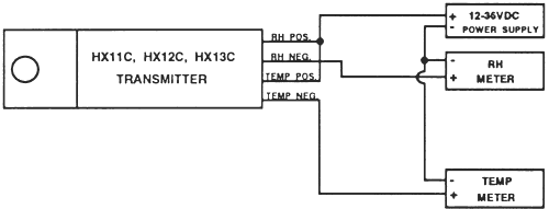
Figure 5-1 shows how to wire up the HX11C, HX12C , HX13C,
and HX21C. Table 4-1 shows the color scheme and pin out configurations
for the transmitters.

Figure 5-1
Wiring Diagram for the HX11C, HX12C, HX13C, and HX21C
Figure 5-2 shows how
to wire up the HX11V, HX12V, HX13V and HX21V. Table 4-1 shows the color
scheme and pin out configurations for the transmitters.

Figure 5-2
Wiring Diagram for the HX11V, HX12V, HX13V and HX21V
RH/TEMPERATURE
CALCULATIONS
To find maximum loop impedance:
|
Rmax
=
|
(V
supply - 12)
|
| |
0.02
|
HX11C, HX12C, HX13C and HX21C
To calculate %RH by measuring current output in milliamperes ( I ):
To calculate temperature
in ░C or ░F:
░C = (I - 4) x 6.25
░F = ((I - 4) x 11.25) + 32
HX11V, HX12V, HX13V and HX21V
To calculate temperature in ░C or ░F from voltage outputs (V):
░C = (V - 1) x 25
░F = (V - 1) x 45) + 32
To
calculate %RH
|
Voltage
units
|
|
Current units |
|
%RH
=
|
(V
- 1)
|
|
%RH
=
|
(I
mA - 4)
|
| |
0.04
|
|
|
0.16
|
|